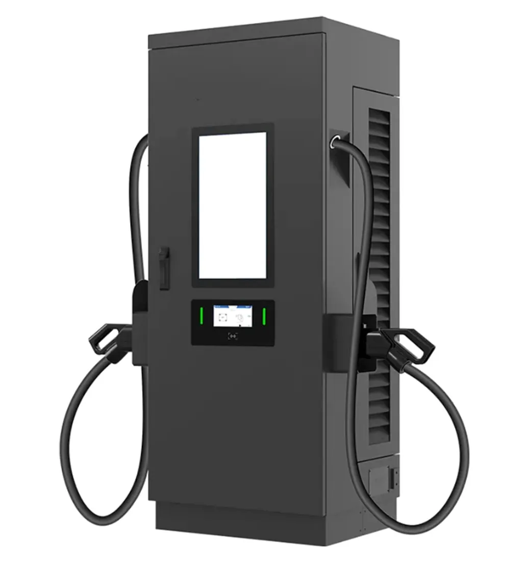
DC fast chargers · 240 kW
240 kW DC Fast Charger: Grid Connection, Cooling and Cable Choices
What a 240 kW dual-connector DC charger needs and delivers: about 258 kVA of supply, 200 A cables, power split between 400 V and 800 V cars.
- Prepared by
- VULTAE Engineering Team
- Published
- Reading time
- 6 min
- Sources
- 2 references
At a glance
- Rated output
- 240 kW DC
- Connectors
- CCS2 + CCS2 / CHAdeMO (IEC) · CCS1, NACS (NA)
- Current per CCS connector
- Up to 200 A
- Input (IEC version)
- 400 V 3-phase, 372 A per phase
- Input (North America)
- 480 V 3-phase, 310 A per phase
- Apparent power
- ≈ 258 kVA
- Cooling
- Forced air
- VULTAE models
- VT-DF240 · VT-DF240-NA
Key takeaways
- 1A 240 kW dual-connector charger is built to keep two cars at high speed at the same time. With 200 A cables, a 400 V-class car peaks at about 80 kW and an 800 V-class car at about 160 kW — so one of each uses the full 240 kW.
- 2Two 800 V-class cars share the cabinet at about 120 kW each; two 400 V-class cars each still get their full ~80 kW, with power to spare.
- 3Supply is the main project item: about 258 kVA per charger (372 A per phase at 400 V, or 310 A at 480 V). One unit usually needs its own transformer; two units fit a 630 kVA transformer only with load management or careful design.
- 4Choose 240 kW where traffic is high and the vehicle mix is moving to 800 V: motorway service areas, busy city hubs and fleet sites with quick turnarounds.

Contents
Short answer: a 240 kW dual-connector DC charger is a two-car machine. With standard 200 A CCS cables, a 400 V-class car peaks at about 80 kW and an 800 V-class car at about 160 kW, so one of each — or two 800 V cars at about 120 kW each — keeps the whole 240 kW busy. Each unit needs about 258 kVA of supply (372 A per phase at 400 V), which usually means a dedicated transformer. It pays off on motorway service areas, busy city hubs and fleet sites with quick turnarounds.
How 240 kW is shared between two cars
The rule behind the chart is simple: power = current × battery voltage. A 200 A cable on a car whose battery sits around 400 V carries about 80 kW; on a car around 800 V it carries about 160 kW. The cabinet adds the two connectors together up to its 240 kW limit.
| Situation | Connector A | Connector B | Cabinet used |
|---|---|---|---|
| One 400 V-class car | ≈ 80 kW | — | ⅓ |
| One 800 V-class car | ≈ 160 kW | — | ⅔ |
| One 400 V + one 800 V car | ≈ 80 kW | ≈ 160 kW | All |
| Two 800 V-class cars | ≈ 120 kW | ≈ 120 kW | All |
| Two 400 V-class cars | ≈ 80 kW | ≈ 80 kW | ⅔ |
Charging times
| Vehicle and situation | Typical average, 10 → 80 % | 60 kWh battery | 80 kWh battery |
|---|---|---|---|
| 400 V-class car | ≈ 65–70 kW | ≈ 35 min | ≈ 50 min |
| 800 V-class car, alone or next to a 400 V car | ≈ 120–140 kW | ≈ 18–20 min | ≈ 24–28 min |
| 800 V-class car, next to another 800 V car | ≈ 100–110 kW | ≈ 22 min | ≈ 30–34 min |
Estimates; the car’s charging curve, battery temperature and starting charge decide the real time — see why a 150 kW charger rarely delivers 150 kW.
Grid connection
| Item | VT-DF240 (IEC) | VT-DF240-NA |
|---|---|---|
| Supply | 230 / 400 V AC, 3-phase, 50/60 Hz | 480 V AC 3P+N+PE, 60 Hz |
| Input current per phase | Up to 372 A | Up to 310 A |
| Apparent power | ≈ 258 kVA | ≈ 258 kVA |
| Typical feed for one unit | Dedicated transformer around 315 kVA, or spare capacity on a larger one | Dedicated service and transformer per utility rules |
| Two units | ≈ 516 kVA — a 630 kVA transformer leaves little margin for other loads; use load management | Same principle |
Three things decide the project budget more than the charger price:
- Transformer and medium-voltage connection — lead times can be longer than the charger’s production time. Apply early.
- Demand charges — two 240 kW units can set a peak of nearly 500 kW even with low daily use. Site-level load management can cap it; see demand charges explained.
- Cable route and protection — 372 A per phase needs large conductors and a properly coordinated breaker; the electrician sizes them from the input current, not from the 240 kW label.
Cooling and cables
The VT-DF240 is forced-air cooled: fans draw air through filtered intakes across the power modules and out of the cabinet. That keeps the design simple and serviceable, with two practical consequences:
| Topic | What to plan |
|---|---|
| Clearance | Keep the air paths free — follow the clearances in the installation manual, especially when placing units back to back |
| Dust and heat | Clean or replace filters on a schedule; in desert or roadside sites, check them more often |
| Cable | 200 A air-cooled CCS cables, 6 m standard, custom lengths available. The cable current, together with the car’s battery voltage, sets single-car speed |
| Noise | < 65 dB — consider placement near homes or hotel rooms |
Where 240 kW pays off
| Site | Why 240 kW |
|---|---|
| Motorway service areas | High traffic, a growing share of 800 V cars, two bays per cabinet |
| Busy city hubs | Ride-hailing, taxis and private cars mixing 400 V and 800 V |
| Fleet sites with short turnarounds | Two vehicles charging fast between shifts |
| Fuel station forecourts with space for one large cabinet | Two fast bays from one footprint |
In the EU, AFIR requires charging pools every 60 km on the TEN-T core network with at least 400 kW total output and at least one 150 kW point from the end of 2025, rising to 600 kW and two 150 kW points by the end of 2027. Two 240 kW units (480 kW) meet the 2025 pool level; a third unit, or a mix with 160–300 kW cabinets, reaches the 2027 level.
For sites with mostly 400 V cars, 160 kW already lets two of them charge at full speed. For heavy vehicles and the highest-traffic hubs in North America, see 360 kW.
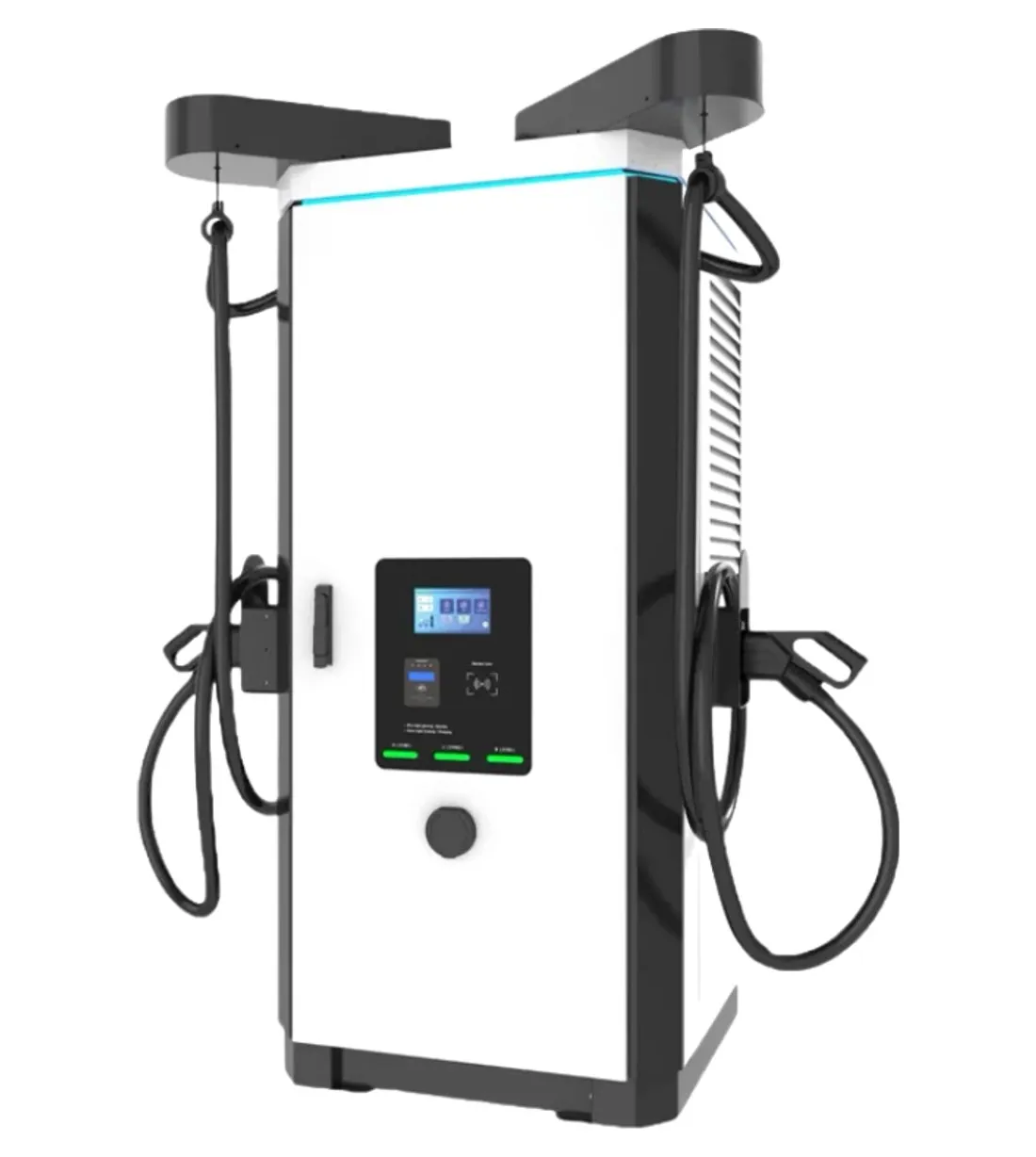
VT-DF240 specifications
| VT-DF240 (IEC) | VT-DF240-NA | |
|---|---|---|
| Max. output power | 240 kW | 240 kW |
| Output voltage | 150–1,000 V DC | 200–1,000 V DC |
| Connectors | CCS2 + CCS2 or CCS2 + CHAdeMO | CCS1, NACS, CHAdeMO options |
| Max. current | CCS up to 200 A; CHAdeMO 150 A | CCS1 up to 200 A; CHAdeMO 150 A |
| Efficiency | ≥ 95.2 % at full load | ≥ 95.2 % at full load |
| Enclosure | IP54 · IK10 | NEMA Type 3R · IK10 |
| Operating temperature | −20 °C to +55 °C | −25 °C to +55 °C |
| Interface | 7″ touchscreen, RFID, QR code; OCPP 1.6J / 2.0.1 | Same |
| Footprint (W × D × H) | 850 × 840 × 1,850 mm (plus 115 mm cable hanger) | Same |
| Options | 21″ advertising screen, POS payment, 22 kW AC output, 4G, C4 anti-corrosion finish | Advertising screen, POS payment, 4G |
See the VT-DF product page for the full range.
Questions buyers ask
- How much power does a single car get from a 240 kW charger?
- It depends on the car’s battery voltage and the cable current. With 200 A CCS cables, a 400 V-class car peaks at about 80 kW and an 800 V-class car at about 160 kW; the car’s charging curve then reduces power as the battery fills. The full 240 kW is used when two cars charge together.
- What transformer does a 240 kW charger need?
- The VT-DF240 draws up to 372 A per phase at 400 V, about 258 kVA. A single unit is typically fed from a dedicated transformer of around 315 kVA, or from spare capacity on a larger one. Your electrical engineer sizes it with the other loads on site and the utility’s rules.
- Is 240 kW better than two 120 kW chargers?
- For the same supply, one 240 kW dual-connector unit can give an 800 V car up to about 160 kW, which two 120 kW cabinets cannot. Two 120 kW units give more redundancy — if one fails, the other still works. High-traffic sites often combine both.
- How is a 240 kW charger cooled?
- The VT-DF240 uses forced-air cooling with filtered intakes. In dusty or hot sites, plan regular filter cleaning and leave the clearances shown in the installation manual around the cabinet.
References
- [1]IEC 61851-23:2023 — DC electric vehicle supply equipment. International Electrotechnical Commission.
- [2]Regulation (EU) 2023/1804 on alternative fuels infrastructure (AFIR). EUR-Lex.