Installation & Power
EV Charger Wire Size by Power and Cable Run Length (Tables)
Cable size for 7 kW, 11 kW and 22 kW EV chargers, with maximum run lengths for a 3% voltage drop in IEC (mm²) and a NEC (AWG) summary. Indicative tables.
- Prepared by
- VULTAE Engineering Team
- Published
- Reading time
- 4 min
- Sources
- 3 references
Key takeaways
- 1Two checks decide the cable: current-carrying capacity (will it overheat?) and voltage drop (is the run too long?). Size for the larger of the two. An EV charger is a continuous load, so it runs at full current for hours.
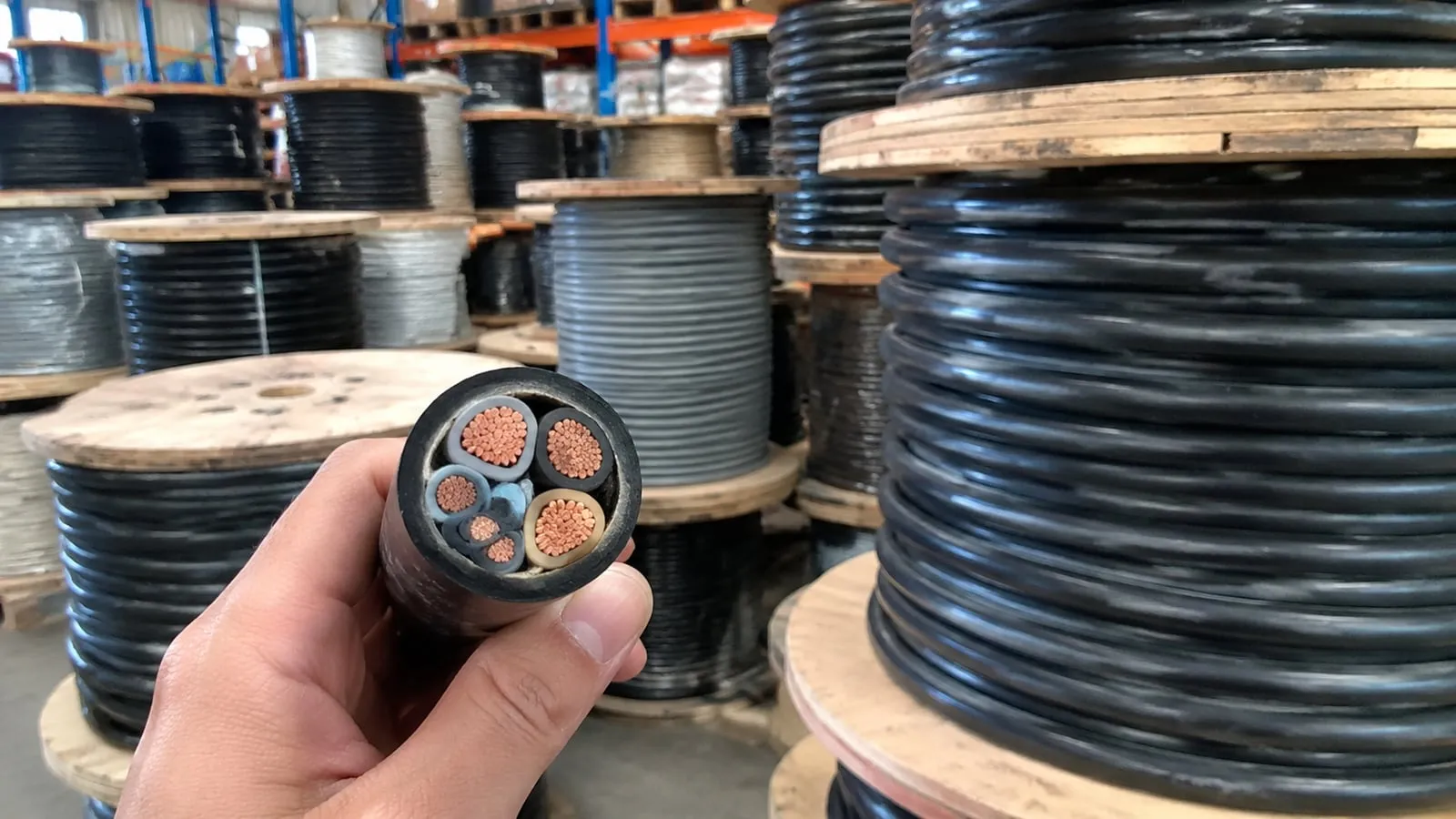
- 2Typical copper sizes (IEC): 2.5 mm² for 16 A, 6 mm² for 32 A, 10 mm² for 40 A, 16 mm² for 63 A — for short runs in common installation methods. Long runs, grouped cables and hot environments need a larger size.
- 3North America: continuous loads are sized at 125% of the charger current (NEC 625), so a 48 A charger gets a 60 A breaker and typically 6 AWG copper.
- 4The tables here are indicative. The electrician must size the cable to the local wiring rules, the installation method, ambient temperature and the protective device.
Contents
Short answer: pick the cable by current (it must not overheat) and then check voltage drop (the run must not be too long). For a 7.4 kW single-phase charger (32 A) a 6 mm² copper cable is the usual starting point; for an 11 kW three-phase charger (16 A per phase) 2.5–4 mm²; for 22 kW (32 A per phase) 6 mm². In North America the breaker is 125% of the charger current. The tables below are indicative — the electrician decides.
Step 1: Charger current
| Charger | Supply | Current | Typical protective device |
|---|---|---|---|
| 3.7 kW | 230 V single phase | 16 A | 16 A |
| 7.4 kW | 230 V single phase | 32 A | 32 A |
| 11 kW | 400 V three phase | 16 A per phase | 16 A |
| 22 kW | 400 V three phase | 32 A per phase | 32 A |
| 40 kW AC / small DC input | 400 V three phase | about 63 A | 80 A |
Step 2: Cable size for the current (IEC, copper)
An EV charger is a continuous load, so base the size on the cable running at full current for several hours. Indicative values for copper conductors in common installation methods (conduit on a wall, or clipped direct), 30 °C ambient, a single circuit:
| Current | Typical copper size |
|---|---|
| 16 A | 2.5 mm² |
| 32 A | 6 mm² |
| 40 A | 10 mm² |
| 63 A | 16 mm² |
| 80 A | 25 mm² |
Grouping cables, burying them in insulation or hot ambient temperatures reduce capacity — the size goes up. The installation standard (IEC 60364) and local rules give the correction factors.
Step 3: Maximum run length for voltage drop
The longer the run, the higher the drop. Keeping drop to 3% is a common design target. The table shows the maximum one-way length for copper at an operating temperature of 70 °C.
Single-phase 230 V
| Current | 2.5 mm² | 4 mm² | 6 mm² | 10 mm² | 16 mm² |
|---|---|---|---|---|---|
| 16 A | 24 m | 38 m | 58 m | — | — |
| 32 A | — | — | 29 m | 48 m | 77 m |
| 40 A | — | — | — | 38 m | 61 m |
Three-phase 400 V
| Current per phase | 2.5 mm² | 4 mm² | 6 mm² | 10 mm² | 16 mm² | 25 mm² | 35 mm² |
|---|---|---|---|---|---|---|---|
| 16 A | 48 m | 77 m | — | — | — | — | — |
| 32 A | — | — | 58 m | 96 m | 154 m | — | — |
| 63 A | — | — | — | — | 78 m | 122 m | 171 m |
A dash means the size is too small for that current. The formula behind the table is simple:
- Single phase: drop (V) = 2 × length × current × resistance per metre
- Three phase: drop (V) = 1.73 × length × current × resistance per metre
Copper resistance is about 0.0225 Ω·mm²/m at 70 °C; divide by the conductor area. Example: 32 A, 6 mm², 25 m, single phase gives 2 × 25 × 32 × (0.0225 ÷ 6) = 6.0 V, which is 2.6% of 230 V.
North America: NEC and AWG
In the US and Canada, an EV charger is a continuous load: the branch circuit and breaker are sized at 125% of the charger’s rated current (NEC Article 625). Typical copper conductors at 75 °C terminals:
| Charger current | Breaker | Copper conductor |
|---|---|---|
| 16 A | 20 A | 12 AWG |
| 32 A | 40 A | 8 AWG |
| 40 A | 50 A | 8 AWG |
| 48 A | 60 A | 6 AWG |
For voltage drop, the NEC gives an informational target of 3% on a branch circuit and 5% overall. Aluminium conductors need a larger size and suitable terminals. Always follow the code edition and local amendments.
Practical advice
- Upsize one step for runs near the length limit, for multi-charger sites or if you may upgrade the charger later.
- Use the charger’s terminal range. Check the maximum cable size the charger’s terminals accept; a very large cable may need a junction box.
- Do not forget earth and neutral. Use the same size for the neutral on single-phase circuits; the earth conductor follows the code.
- Think about the protection. The breaker must protect the cable; see RCD requirements and surge protection.
- Use a calculator for the final numbers — see the breaker and cable size calculator once it is published, and the installation requirements guide.
Supply, not only cable
The supply must carry the load. If the charger shares a supply with the building, dynamic load management can reduce the cable and the supply upgrade you need. And if your supply is single phase, a 22 kW charger will deliver only about 7.4 kW — see single-phase vs three-phase.
Questions buyers ask
- What size cable do I need for a 7 kW EV charger?
- A 7.4 kW single-phase charger draws 32 A. In IEC countries 6 mm² copper is the usual choice for short to medium runs, protected by a 32 A device, and 10 mm² for runs beyond roughly 30 m. Confirm with the installer.
- What size cable do I need for an 11 kW or 22 kW charger?
- An 11 kW three-phase charger draws 16 A per phase, so 2.5 mm² to 4 mm² copper is typical. A 22 kW charger draws 32 A per phase; 6 mm² copper is typical for runs up to about 50 m, and 10 mm² for longer runs.
- How much voltage drop is acceptable?
- Many codes suggest keeping drop on a branch circuit to about 3%, and 5% for feeder plus branch together. Excessive drop wastes energy and can make the charger derate or trip on under-voltage.
- Should I choose a bigger cable than the table says?
- Often yes. A larger cable costs more up front but wastes less energy, runs cooler and allows a power upgrade later. For a long run or a multi-charger site, upsizing is usually worth it.
References
- [1]IEC 60364-7-722:2018 — supplies for electric vehicles. International Electrotechnical Commission.
- [2]NFPA 70 (National Electrical Code). NFPA.
- [3]IEC 61851-1:2017 — general requirements. International Electrotechnical Commission.